Contents
- Burney Rifle (‘EM-4’)
- Hall Rifle (EM-3)
Burney Rifle
Here are some notes on the Burney Rifle, sometimes referred to as the EM-4, a bullpup rifle from 1945.
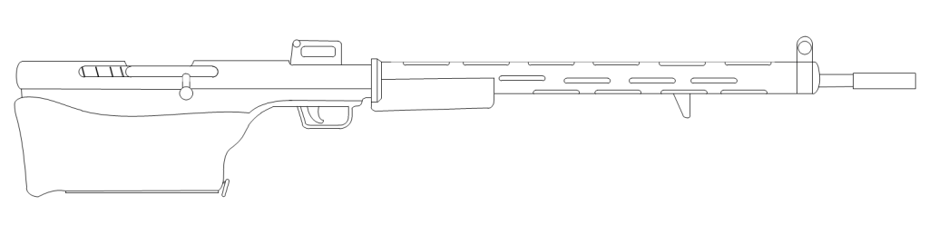
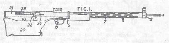
Burney Rifle, based on the patent drawing
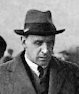
The Burney Rifle was designed by Sir Charles Dennistoun Burney (1888-1968)[1], a prolific inventor and the chairman of his investment company, the Broadway Trust Company Ltd (1924-1960)[2], working with ICI and the Ministry of Supply.[3]
Tony Edwards [4] provides excellent information on the development of the ammunition. During the Second World War, Sir Dennis Burney was working on high velocity guns, with an interest in improving the ballistics of the .303 cartridge. A perforated .303 cartridge case was drawn in June 1941, development was under way in March 1942, and evolved from a .25 to a .27 round.
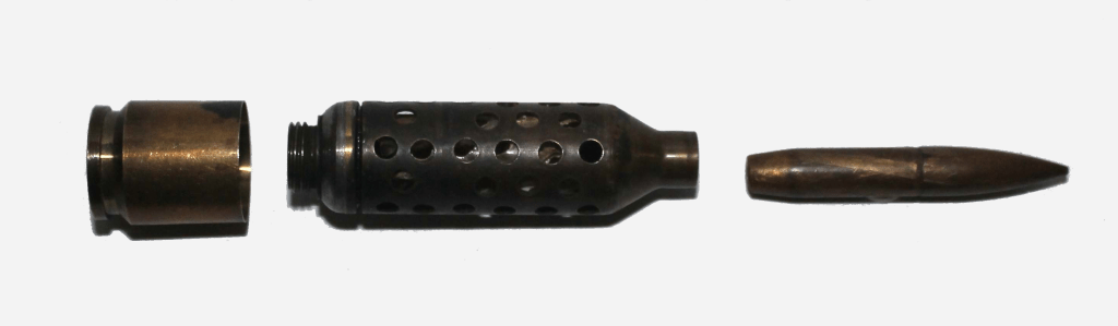
Three-part cartridge with skirt, perforated case and bullet
The cartridge developed in 1944/45 was the 7 x 55mm ‘.270 Broadway Trust Company (BTC) Experimental’ with a perforated case so that the propellant gases could expand into an enlarged chamber. It resembles the perforated cases of recoilless weapons of the type Burney was experimenting with.
The bullets were very long at 44-45mm (~6.4 calibres), with three known weights at 200 and 206 grains, both lead alloy core, and 167 grain with a steel core (12.96, 13.35 and 10.82 grams respectively). A drawing shows the bullet diameter as .274 and length 1.745 inches. At a muzzle velocity of 2570 fps (783 m/s), if this was achieved with the heavier bullet, this gives an impressive muzzle energy of 4.1 kJ. Further, the bullets had exceptionally high Sectional Density, again, for the heavier bullet this was 0.4 (0.029 lb / 0.27^2 inch). If the Form Factor was as high as say, 1.9 then this indicates a BC 0.74, meaning that a lot of energy would have been carried downrange (using BC=SDxFF from [3]).
The Ministry of Supply calculated that a bullet equivalent in weight to .303 Mk VII, at 174 grains (11.3g), could achieve 2900 fps (884 m/s). This would give an extremely high 4.4 kJ muzzle energy (a third more than the SMLE), and commensurate high recoil. The rifle was therefore designed to reduce recoil.
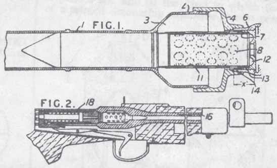
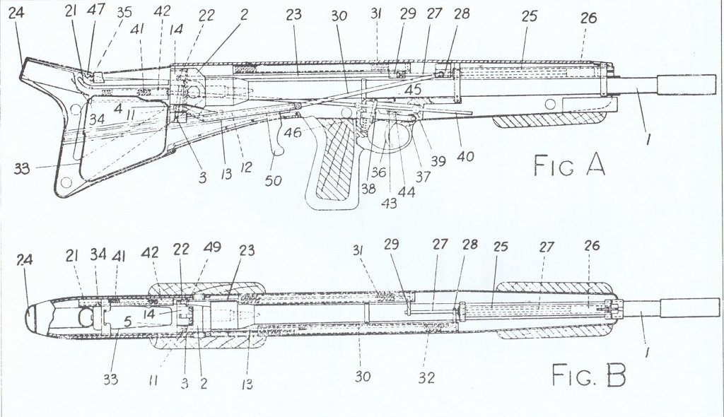
The rifle shown is described in the patent abstract ‘Improvements in or relating to rifles’ of 28 May 1945.[5]
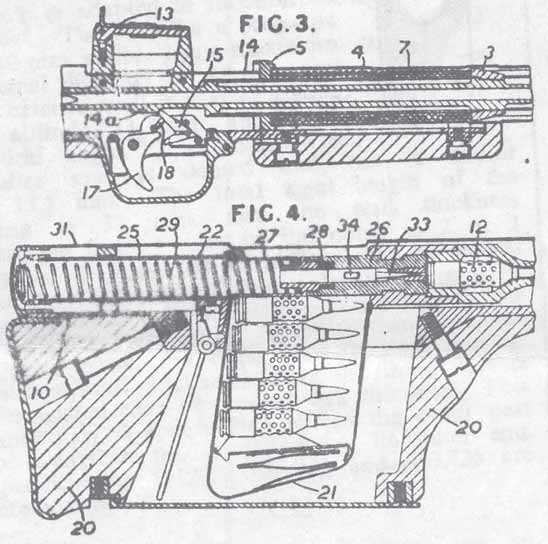
‘A semi-automatic recoil-shock absorbing rifle’ based on the patent drawing
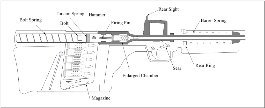
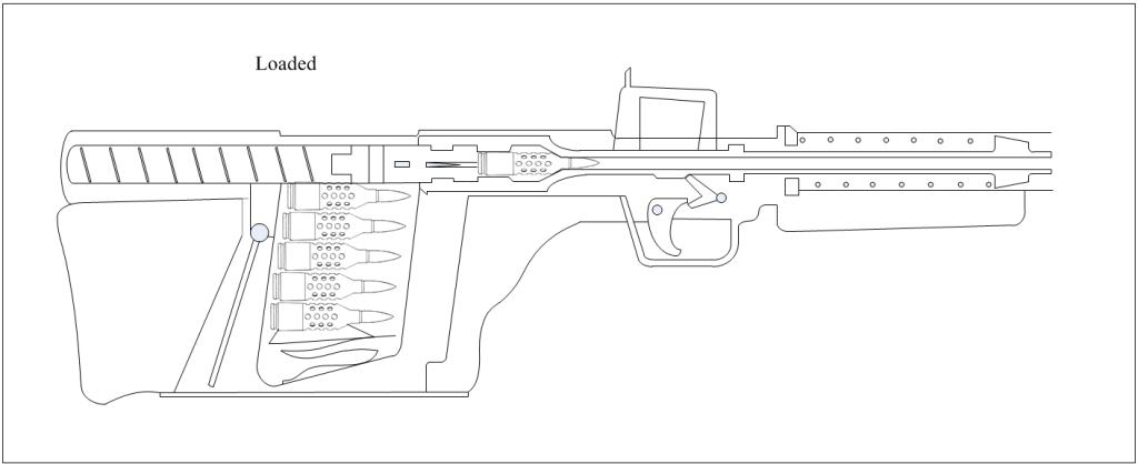
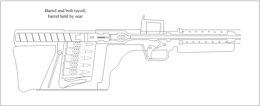
The action is short recoil, and is as follows:
- When loaded the barrel is held to the rear by the trigger sear, against the force of the barrel spring, with the round chambered and bolt locked.
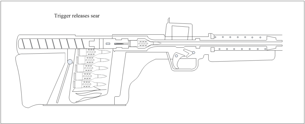
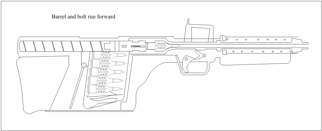
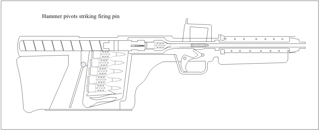
- When the trigger is pulled the sear is dropped and the barrel, bolt and magazine all run forward due to the barrel spring. Before reaching the fully forward position, the pivoted hammer hits a fixed cam and strikes the firing pin.
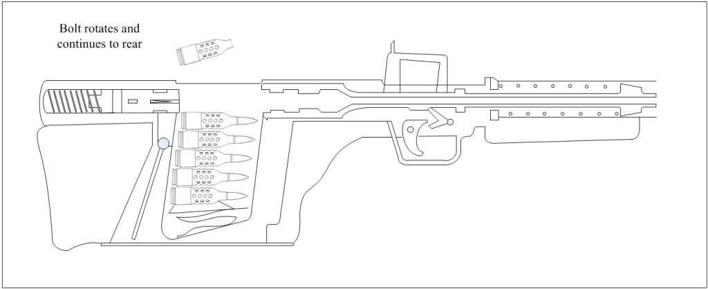
- As the barrel and bolt group recoil, a cam forces the bolt handle up, rotating the splined bolt head out of lock, which continues to the rear. A claw extractor and spring ejector remove the spent cartridge.
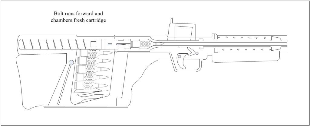
- The bolt spring runs the bolt forward and chambers a round. The bolt head is relocked by a torsion spring between the bolt halves.
This series of images show the cycle:
The two points of interest in the design are in using differential recoil and an enlarged chamber.
Differential recoil has been used in light artillery pieces, such as mountain guns,[6] and had been used in the PIAT. In this case the recoil from firing must arrest the forward momentum of the barrel, bolt and magazine before accelerating them to the rear.
The enlarged chamber, ‘which acts as a reservoir’, reduces peak chamber pressure. This is explained in a few of Burney’s patents: ‘a clear annular space is formed around the cartridge case into which the explosion gases can pass, thus reducing the maximum pressure, but producing a higher mean value of the pressure space curve’, and that the chamber volume ‘lies within the range of 25-50 per cent of the barrel volume.’ The high mean pressure permits a long barrel. The principle, a type of high-low pressure system, was used on the German PAW 8H63 lightweight anti-tank gun in 1944.[6] Burney’s interest may stem back to earlier in the war[7] when he was experimenting with propellants to yield a flatter pressure curve in recoilless guns.
This graph is given in a Burney patent on a ‘controlled pressure’ weapon with an enlarged chamber.[8] It shows that compared to a conventional chamber (A), an enlarged pressure chamber (B) gives reduced peak chamber pressure and higher mean pressure.
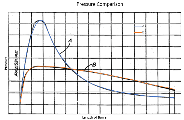
My overlay is not that close, as the gridlines diverge, but there is a slightly higher mean pressure in B than A (3.21 ‘pressure units’ to 3.15).
Scaling the weapon from a patent sketch is clearly speculative, especially as the starting measurement is a 55 or 56mm case. However, from this the pull looks like a convincing bullpup distance of 0.39m. The overall length is not unusual at 1.15m, but the barrel length is extreme at >0.8m, longer than an MLE.
Continuing the speculation, one might think that this is a post-war, experimental bullpup in 7mm, in the same category as the select-fire EM-1 and EM-2 assault rifles that used an intermediate cartridge (albeit quite a powerful one). Instead this appears to be a semi-auto rifle with a generous case capacity and an exceptionally long bullet, a very long barrel and high muzzle energy, with measures undertaken to reduce the recoil. It perhaps owes more to the Pattern 1913 / .276 programme than the post-war assault rifle programme.
The rifle was ready at the end of 1945 but the trials, discussed in February 1946, had obturation problems until a separate brass skirt was fitted. In late 1946 twelve rifles were ordered from RSAF Enfield, but the order was suspended. The rifle exhibited problems with the bolt, trigger, striker and poor accuracy due to bullets slipping in the rifling due to poor bullet and barrel tolerances.[4] The differential recoil timing was problematic.[3] Trials continued in 1947 but failed to show sufficient promise, and the project was closed in March 1948.[4]
Burney’s work on recoilless weapons led to the 3.45 inch RCL.
[1] https://en.wikipedia.org/wiki/Dennistoun_Burney
[2] University of Glasgow Archive Services GB 248 UGD 100/6. BTC Ltd was incorporated in Broadway, Westminster in 1924.
[3] Williams, Anthony G. and Popenker, Maxim, Assault Rifle, 2004
[4] Edwards, Tony, The Cartridge Researcher, No.554, June 2011. Tony in turn quotes Ordnance Board Proceeding Q.6,234, 4th October 1949; and Meeting at ICI Ardeer, 27th February 1946. The trial discussed February 1946 produced muzzle velocities in the range 2074-2488 fps. See also Edwards, Tony, The Broadway Trust Company, IAA Journal issue 477, January/February 2011
[5] UK patent 645751. Note in the slightly earlier patent 643842 ‘Improvements in or relating to rifles or other quick firing guns using fixed ammunition’ of 13 March 1945, a rifle is described as having a magazine inserted from the left-hand side.
[6] Hogg, I.V., A History of Artillery, 1974, see also https://en.wikipedia.org/wiki/High%E2%80%93low_system
[7] UK patent 590270, 18 November 1942
[8] US patent 2489748 ‘Controlled pressure gun’, filed 6 September 1945
Some notes on the design: The description states that to load, the bolt handle is rotated and then retracted, but as this is attached to the bolt head and it would not compress the barrel spring as described, this would seem to be in error. The accuracy achieved with a differential recoil system is not described. One consequence of the rear sight mounting is that it also runs forward and would perhaps momentarily obscure the target. There does not seem to be so much as a hole for the thumb of the trigger hand. The patent drawing indicates the bolt turning cam and a safety without clearly showing the mode of operation. The bolt handle being turned up by a fixed cam is similar to the mechanism of the Soviet PTRD-41.
My thanks to Tony Williams. 20th January 2020.
See https://forums.delphiforums.com/autogun/messages/?msg=7588.1 and https://en.wikipedia.org/wiki/EM-4_rifle
Hall Rifle EM-3
John Eric Mounsey Hall (1909-1989) was born in Melbourne, Australia and became a lieutenant (on probation) with the 58th Battalion ‘Essendon Rifles’ in 1930 as a part-time member of the Militia. With the outbreak of the Second World War he was seconded to the Australian Imperial Force in the Middle East and was wounded in action. After the war he was part of the Royal Australian Army Ordnance Corps, retiring as a lieutenant-colonel in 1962. [1]
Whilst on the War Course at RMCS Shrivenham, Major Eric Hall designed a bullpup rifle that was patented on 5th February 1945. [2] It is understood that a mock-up was constructed from wood and although it did not go further it is often referred to as the Experimental Model EM-3. [3]
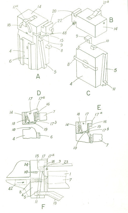
The sketch is based upon the patent abstract, which is open to interpretation.
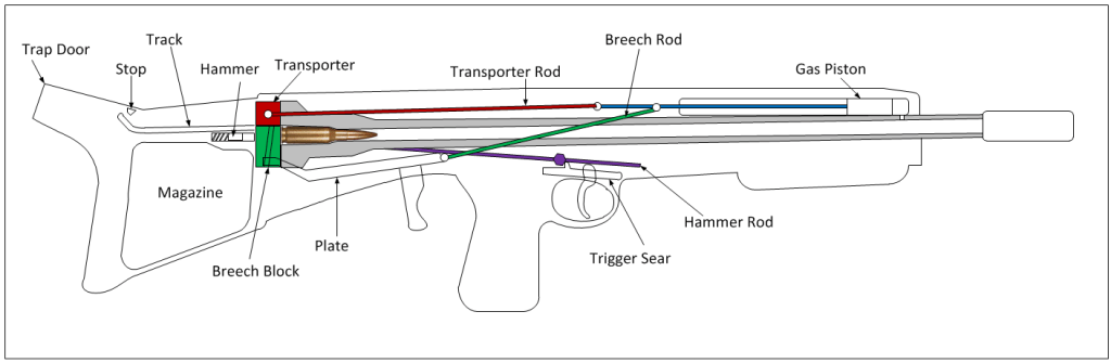
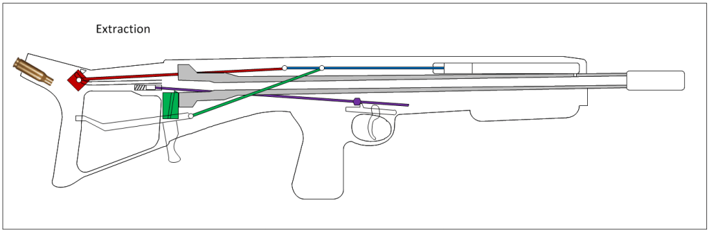
The EM-3 Hall Rifle is a bullpup rifle with a long barrel to overall length ratio. The weapon can be fired from the shoulder left- or right-handed as the cartridge cases eject over the shoulder. The function of the bolt is split into two, with a falling breech block and a separate cartridge transporter being used to extract and load cartridges. As such the gas piston rod (shown in blue) acts on two operating rods: the first is the breech block rod (shown green) that runs down the right-hand side of the rifle, and to which the charging handle is connected; the second is the cartridge transporter rod (shown red) that runs along the left-hand side of the weapon to a pin on the transporter. Both of these rods are held forward by springs. The hammer is held back by a trigger sear and the hammer rod (shown in purple) that also lies on the left-hand side.
This series of images show the cycle:
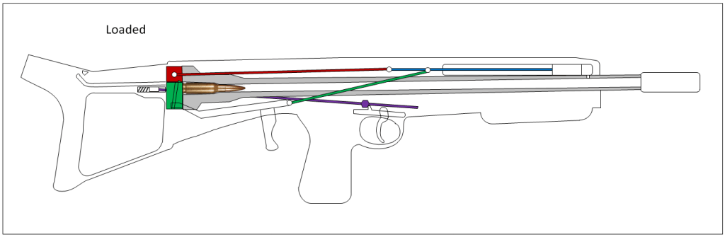
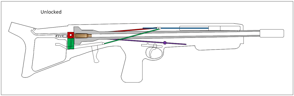
- When the trigger is pulled the sear drops and releases the hammer rod and the sprung hammer
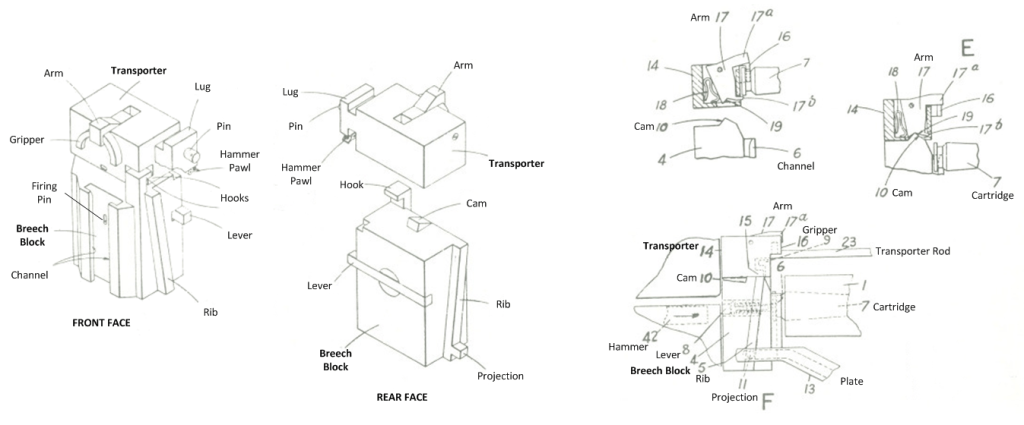
- The hammer flies forward and strikes a lever that projects from the left of the breech block and drives a firing pin through the breech block to fire the cartridge
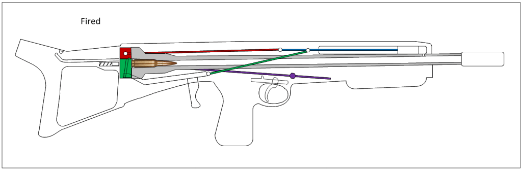
- Gas pressure drives the gas piston back
- The breech rod pushes the plate back, this plate has a groove or slot into which fits a projection from the breech block. The slot runs horizontally for a small dwell time, then tracks downward to pull the breech block down. The inclined ribs on either side of the breech block run in inclined slots in the receiver
- As the breech block descends, the cartridge, held in the channel of the front face, is pulled slightly from the chamber. With a hook the block also pulls down the transporter and this has a semi-circular gripping member that engages in the extractor groove of the cartridge.
- At this point the crosshead of the gas piston reaches the transporter rod and starts to push it to the rear
- The hooks that hold the transporter to the block disconnect and a lug on the transporter guides it backward along a track
- As the cam on top of the breech block slides out from the bottom of the transporter, a sprung arm in the transporter grips the empty cartridge case
- A pawl in the transporter lug re-cocks the hammer, and a separate sear holds it back if the trigger has not been released
- The gas piston stops and the transporter continues under inertia
- When the transporter reaches the end of the track, a fixed stop strikes the arm, releasing the cartridge case which then ejects out of the trap door and over the shooter’s shoulder
- Under spring force the transporter now runs forward again, collecting a new cartridge from the magazine and holding it with the arm
- The breech block has been held down by a pawl until the hooks re-engage. At this point the cam is inserted into the transporter and the arm releases
- The transporter and breech block move up together, the channel passing into the extractor groove of the cartridge, until the breech is closed
It is possible the problem set at Shrivenham was to design a bullpup that could be fired left- or right-handed. I could imagine this design starting with a single operating rod, evolving to have two fixed to the gas piston, and then the need to have the transporter move independently required the hold down pawl to bring the components and timing back together. The geometry here seems slightly off as the charging handle looks like it travels too far back. With a rod in compression, the trigger mechanism may have been more responsive than a linkage put in tension. The vertical movement of the transporter bears some similarity to that in the Maxim/Vickers gun. Automatic fire is not described.
[1] The Age (Melbourne, Victoria) Thursday 6th February 1941; Commonwealth Gazette. Photograph courtesy Andrea Lowenthal.
[2] UK patent 589394
[3] Tony Edwards
See also Historical Firearms
27th January 2020.
It is possible Korobov took inspiration from the Hall patent in designing his TKB-002PM. This is also a very compact bullpup with a falling breech block and separate transporter – though in this case it throws the spent cartridge cases forward through a trapdoor to permit left- and right-handed shooting. https://en.wikipedia.org/wiki/TKB-022PM
10th February 2025
